Axial Probe Gap Voltage Feed Pump
Why is vibration monitoring important? Vibration is the language of machines.
Machines are always trying to tell us how they feel, but they speak their own language. If we were able to understand the machine's language, our life would be much easier and machine life would be much longer. Simply put,machines vibrate due to forces acting on them, and the characteristics of the vibration can tell us important information about their condition.
Vibration Measurement Through The Years
Looking back into the history of vibration measurement, you can see these two technicians in the pictures below using two methods that were a lot more common than you might think.
Technician on the left is using Fish Tail Method: Also known as a shaft stick - a fish tail is just a piece of wood with a v-shaped notch that fits against a rotating shaft. The wood is soaked in lubricating oil so that it doesn't stick or chatter against the shaft (a small amount of smoke from frictional heating is normal). A technician holds the stick against the rotating shaft (carefully!) and judges the level of vibration by feel or by using a simple mechanical or electronic sensor mounted on top of the stick. This method seems crude by today's standards, but it did provide some level of vibration data collection at the time.
Our other technician on the right is using Screwdriver Method: He is using a screwdriver to isolate the location of vibration in a machine. The screwdriver provides a conductive path to transmit audible vibration to the technician's ear. This method does have some value, but the main drawback is that it depends on the technician's experience and memory.
It wasnot easy to quantify data when it only exists as a vague description of sound. These two methods are not very sensitive to small changes, and the results vary widely based on the person making the observation. They do not provide very reliable indications of deteriorating machine conditions. In the end, machines are our babies and we want to make sure they live a healthy life!But the question is, how do we do that?
With modern technology, it is possible to detect and record vibration signals using electronic sensors rather than just listening with a screwdriver.
The vibration of a machine can tell us important information about its health and the characteristics of the vibration can help us detect and diagnose symptoms before they become severe. Vibration is the response from forces acting on the machine. Machines vibrate differently so, different vibration transducers are available.
What is Vibration?
This article will focus on:
- Basics of vibration
- Transducer types
- How to choose the best tool for you
First of all, let'sdefine vibration:
Vibration is an oscillating motion relative to a reference plane of measurement and most importantly it is a result of force.
How is Vibration Measured?
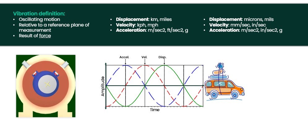
Machine vibration is typically measured and reported in terms ofDisplacement,Velocity, andAcceleration.
- Displacement is the distance traveled. For cars, we use large units such as km or miles. For vibration, the distances are very small, so we typically use microns (1/1000 mm) or mils (1/1000 inch).
- Velocity is the Time rate of change of displacement. For transportation, we use large units such as km/hr or miles/hr. For vibration, It is measured in mm/s or IPS.
- Acceleration is the Time rate of change of velocity. For transportation, we use large units such as m/s2, ft/s2, or "G" which is the acceleration of gravity . For vibration, we use m/sec2, in/sec2, or most commonly acceleration of gravity "G".
Remember that vibration is not just magnitude, it also includes a direction – similar to east or west directions traveled by automobile, or the vertical axis measured by the machinery vibration sensor shown below.
A quantity that has both a magnitude and a direction is called a "vector" and Displacement, Velocity and Acceleration are all vectors.
In the car example; after you start your car, you first accelerate using the acceleration pedestal, then you gain velocity to reach the distance you want. So, acceleration leads velocity and velocity leads displacement.
The same is true in machine vibration.
The plot below is called a timebase plot, which has the amplitude onY-axis and time onX-axis. The time is increasing from left to right and we can see the positive peak of acceleration happening before the velocity, and the velocity positive peak happens before the displacement.
When we measure the movement of the machine housing, we are measuring movement caused by forces. These forces are transmitted through the bearing to the machine casing, causing it to accelerate according to the magnitude of the forces and the mass of the casing.
The acceleration (which is a function of force) results in the velocity of the case movement (which proportional to fatigue) and displacement of the case (which is proportional to stress).
What is a Vibration Signal?
People used to ask; "How much is the vibration?" Really! It's just like asking a person how old is he and assuming that a young 21 years old person must be in a healthy condition.The degree of vibration in and of itself is not an indicator of a machine's health. We need some context first.
In reality; we need to know5 parameters to describe a vibration signal and correlate them to the process parameters to properly manage our machines. These are:
- Direct amplitude - the measure of the total amplitude of the original signal. For example, the waveform in the figure below is a direct, or unfiltered, waveform and we can measure the amplitude from the pk-to-pk as 2.9 mils Pk-Pk.
- Frequency - the content of the signal may give us clues as to what category of possible malfunctions the machine is experiencing. The waveform is a complex waveform consisting of multiple frequencies, some experienced technicians can tell that it is a 1X and 5X, however, it is easier - and more reliable - toget this information from another plot called a spectrum plot. (hint: there is also a 2X component, did you notice it?)
- nX amplitude and phase: When we break the vibration signal into discrete frequency components, we can measure both their amplitude and phase. The waveform in the image below represents the filtered 1X WF of the previously mentioned waveform (above), and we can tell the amplitude is 2.0 mils pk-pk. Also, the keyphasor® signal which is represented by small dots on the waveform is considered a timing reference. Knowing that the complete vibration cycle is 360 degrees, and that phase is measured from the key phasor event to the next positive peak, we can tell that phase is ~10 degrees.
- Position is the dc component of the displacement transducer, which will be discussed in the proximity transducer section of this article. Position information can be very important in analyzing certain machine malfunctions (e.g., misalignment and instability).
- Shape or form - just like a picture of a person. We cannot describe a person only by his weight and height. We could, but you'd have a hard time identifying an individual. How about the eyes size and color, hairstyle and length, nose, and more? Knowing the subtle variations in the shape of a vibration leads to a greater degree of accuracy in diagnosing the source, the underlying cause, and then the appropriate action to take. Similarly,amplitude, frequency, and phase information combine to give us a characteristic shape or form of the vibration. The form of the vibration signal can sometimes highlight significant changes that individual signal measurements might not be able to do it alone.
Vibration Sensors: Types and Uses
So, we can measure vibration in terms of Displacement, Velocity, and Acceleration. Buthow do we accurately collect and transmit these measurements? What are the sensors used? How do they work? Knowing how the vibration signal originated will help you in diagnosing vibration issues and differentiating between instrumentation issues and real vibration problems.
We will discuss the vibration transducers one by one, so let's start with Displacement.
Displacement Transducers
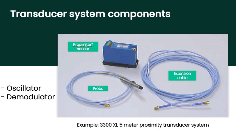
This is a typical Bently Nevada proximity transducer which consists of a Proximitor proximity sensor, extension cable, and probe. But how does it work? And what makes it a non-contact probe?
How Proximity Sensors Work
The Proximitor† Sensor performs two basic functions: First, as a tuned oscillator which generates a radio frequency (RF) signal. This signal produces the low-energy electromagnetic field around the probe tip.
Then, the Proximitor† Sensor performs as a special demodulator circuit which conditions the RF signal to extract a usable displacement signal from the feedback. When a conductive material is present in the RF field, the alternating electromagnetic field induces small eddy current flows in the surface of the shaft. The penetration depth of the eddy current depends on the material's conductivity and permeability.
When the shaft (or conductive material) is within the linear range of the probe, eddy current flows in the surface of the shaft material and the RF will have lower amplitude. So, the first probe below shows the condition when the probe is very far away from the shaft, which means that the RF amplitude is maximum. This is the condition before mounting the probe in place.
When your instrument team installs the probe, they try tokeep the gap between the shaft and the probe tip in the middle of the linear range, so when the shaft vibrates towards or away from the probe, it remains in the range that the transducer can see. This means that the eddy current is now generated on the shaft surface and that's why the RF amplitude is lower in this next image.
Finally, when the shaft vibrates, as below, the shaft gets close and away from the probe causing the RF to be modulated with the same vibration amplitude.
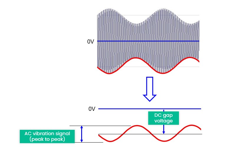
The demodulator circuit (in the Proximitor†) extracts the modulating signal from the RF signal. Just like the radio in your car, the demodulator circuit performs the same function as a radio receiver. The main difference is that the radio receiver amplifies the extracted modulation signal (music or voice) and plays it over a loudspeaker for our listening enjoyment, while the Proximitor† Sensor sends the extracted vibration signal to the Vibration Monitoring and Machine Protection system.
As you can see in figure to the right, the red waveform represents the vibration as two important parameters AC & DC. The AC component represents vibration whereas the DC component represents how far the average of the AC is, from zero. So, the DC component can tell us how far the shaft is from the probe tip during vibration. At the "stopped condition", the AC will be zero and DC will tell us the gap between the probe and the shaft.
- Time-varying (AC) value is the vibration signal
- Average (DC) value is the gap voltage
Proximity Probe Applications
Traditional vibration measurement is not the only application for proximity probes; they can be used for many other applications:
- Radial Vibration - which is the shaft movement, as discussed earlier.
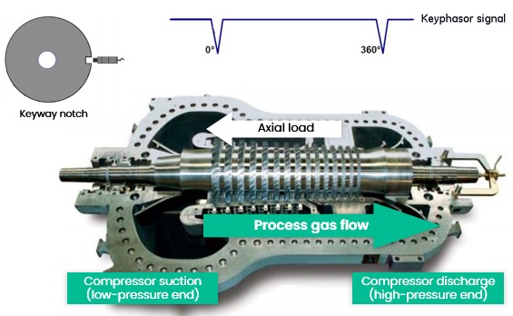
- Axial or Thrust Movement - this will happen in rotating equipment and measurement. This is a vital metric for analysis and protection. The compressor on the right will normally move from right to left due to process load as the high-pressure pushes the shaft towards the low-pressure side.
- Key Phasor - this is a once per revolution reference signal, used to measure phase and speed. We can obtain KPH reference by having a single notch, or projection in the probe target area which will give pulse at the same angle of the shaft during rotation. When the KPH signal is combined with a vibration signal, we can tell at which angle the shaft was when it was closer to the vibration probe. This is called the absolute phase angle.
- Rod drop and rod position - these are special measurements for reciprocating machines, which shows how much the rod has dropped if measured vertically only or the actual position of the rod if measured with two probes.
- Differential expansion - this measures the difference in expansion between the rotor and casing. This is a very important parameter for some machines like gas turbines and steam turbines.
- Eccentricity -this metric represents the shaft bow. Some machines are subject to rotor bow, like steam turbines, and we need to measure how much the rotor is bowed before we start the machine. Obviously, severe bow can damage the machine during startup.
-
The linear range of the proximity probes depends on the probe tip diameter. The bigger the probe tip diameter, the longer the linear range it can measure. For example, a 50 mm probe can measure a longer range if compared with a 5 mm probe. Also, proximitors are calibrated for a specific target material and system length, that's why the probe length + the extension cable lengthMUST match the proximitor calibrated length and weMUST use a proximitor calibrated for the target material.
Velocity Transducers
- Design: either a moving coil sensor or an accelerometer with onboard integrating circuit
- Operation: moving-coil design is self-powered, but piezoelectric design requires a power source
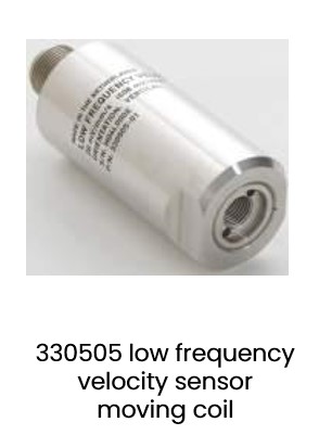
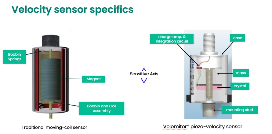
Velocity sensors have traditionally been used for machinery condition monitoring and earlier designs used a coil of wire that moved relative to a permanent magnet which you can see on the left.Moving-coil velocity sensors provide a very strong, low-noise signal making them ideal for low-frequency applications.
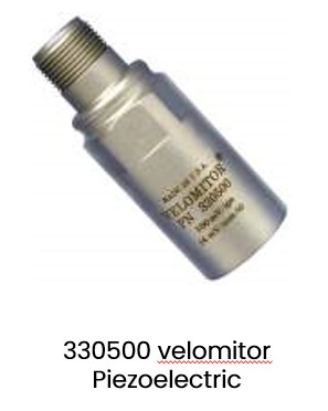
Newer piezoelectric velocity transducers are simplyaccelerometers that incorporate signal integration circuitry inside the sensor case. These devices provide an output signal that has already been integrated into units of velocity.
The fact that the acceleration-to-velocity integration step is performed byon-board electronics inside the sensor eliminates the chance for noise to be introduced along the field wiring between the sensor and monitoring system.
Above you can see details of the two sensors.
Moving-coil sensors are only accurate in the orientation angle they were designed for. E.g. If a sensor designed for vertical operation is installed horizontally, the delicate springs may allow the coil to physically drag against the magnet, introducing large response errors.
The moving coil sensors are "self-generating" devices, which means they produce their signal without the need for external power.
On the other hand, in newer piezoelectric designs, vibration causes a periodic deformation of the internal piezoelectrical crystal element which produces a charge difference between opposite faces of the element. This tiny charge difference which is related to acceleration is amplified (and integrated to velocity using an internal circuit) and the current or voltage signal can effectively be transmitted through field cable to the vibration monitoring system.
Piezoelectric velocity sensors require external power for the electronic amplifier and integration circuits to work. However, they are a "solid-state" devices and have no moving parts making them very robust and reliable.
As a side note, it is also possible to detect vibration with an accelerometer sensor and then integrate the signal to velocity units in the vibration monitoring instrument, or via vibration analysis software. But the advantage of performing this integration within the sensor case itself is that the acceleration signal only needs to travel a very small distance to reach the integration circuitry, so there is much less opportunity for external noise to be introduced into the signal.
Acceleration Transducers
Accelerometers are also utilizing the piezoelectric crystal element, so vibration causes a periodic deformation of the internal crystal element which in turn produces a charge difference between opposite faces of the element. This tiny charge difference which is related to acceleration is then amplified to a much larger current or voltage signal that can effectively be transmitted through field cable to the vibration monitoring system.
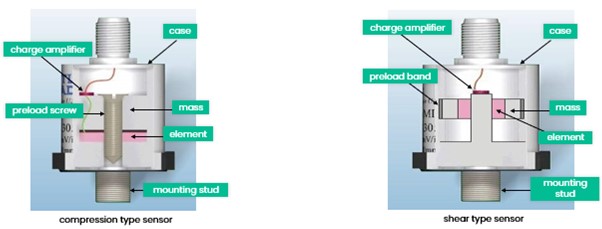
These illustrations above show the difference between the older compression type design on the leftand thenewer shear-type design for a piezoelectric accelerometer on the right. The sensing element in the compression design is squeezed between a reference mass and the bottom of the sensor casing. The shear-type accelerometer contains a ring-shaped element mounted to a cylindrical post. It is surrounded by a ring-shaped reference mass and preloaded by a clamping band. Shear-type sensors are much less susceptible to thermal stresses and to distortion of the lower sensor case.
Seismic Transducers
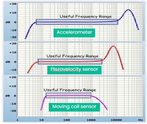
Accelerometers, piezovelocity sensors, and moving coil sensors are all called seismic transducers. The generic transducer response curves in the figure to the right compare the characteristics of three general-purpose seismic transducers over a wide range of vibration frequencies.
Accelerometers typically have a more extended high-frequency capability than piezovelocity sensors, whereas the moving coil sensors have a very limited linear range.
- Accelerometer : highest frequency response. Used for gear mesh, impulse, and other high-frequency applications.
- Piezovelocity sensor : lower high-frequency response, but less noise than using an external integrating amplifier with an accelerometer.
- Moving coil sensor : more limited-frequency response, but has no requirement for an external power supply.
Note: In the history of vibration analysis, moving-coil velocity sensors were invented and used long before piezoelectric sensors were perfected. So, many years of analysis and studying of velocity data has resulted in vibration monitoring guidelines (such as some vibration standards) that include recommended severity levels based on units of velocity rather than acceleration.
Transducer Positioning Examples
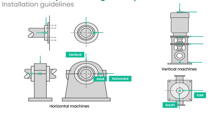
No matter what type of seismic transducer we use, when installing seismic transducers on the machine,usually 3 transducers are installed at each bearing to record three key metrics: Horizontal, Vertical, and Axial.
Transducersshould be located as close to the bearings as possible, and at the points of most direct transmission of forces from the rotor to the casing. It is important to avoid installing them on parts of the machine (such as access covers) which may be vibrating with local resonances that do not represent the vibration of the bearing housings. Examples* of recommended locations are below.
*The Reference of these examples is ISO Standard 10816-3
Transducer Selection
Rotating machinery come in many different designs and are used for different applications, like small motors, pumps, compressors, large steam turbines, generators, and many more. Machine construction can be broken down into categories based on the type of bearings used.
There are many types of bearings, however,we will discuss the two major bearing types used in the industry: fluid film bearings and rolling element bearings (REB).
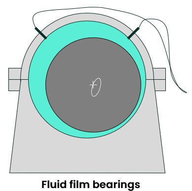
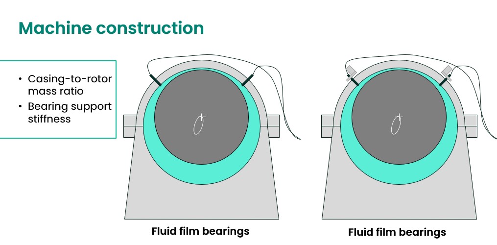
Fluid film bearings (which is on the left side here) usually transmit a relatively small amount of vibration from the rotor to the casing. This is because the rotor is supported by a fluid wedge and there is no metal-to-metal contact between the bearing and the rotor when the machine is operating correctly. In this scenario; a relatively large amount of vibration energy transmitted to the fluid is dissipated and not transmitted to the machine casing.
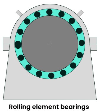
Rolling Element Bearings typically provide a high degree of vibration transfer from the rotor to the casing due to the direct metal-to-metal contact of the bearing elements, as the rotor is rigidly connected to the bearing inner race which is supported by the rolling element.The rolling elements transfer the load of the rotor to the outer race. The outer race is supported by the bearing housing and the bearing housing is typically a press-fit to the outer race.
We also need to consider casing-to-rotor mass ratio and bearing support stiffness.
Heavy casing/Light rotor: this is the condition where the casing-to-rotor ratio is greater than 10:1. In this instance, it is very unlikely that vibration originating at the rotor will be transmitted to the casing.
Similarly,when the support is "stiff", the casing would experience minimal amount of motion; hence, XY proximity transducers are the appropriate choice.
Light casing/Heavy rotor: this is the condition where the casing-to-rotor ratio is less than 5:1. In this instance, it is possible for the rotor to generate sufficient force to cause the casing to vibrate.
Similarly,when the support is"soft" (aka - complaint support) significant casing motion will probably occur. It is recommended to use dual XY probes and measure for absolute shaft vibration. Dual XY probes involve measuring casing vibration and shaft relative vibration in order to identify the absolute shaft vibration.
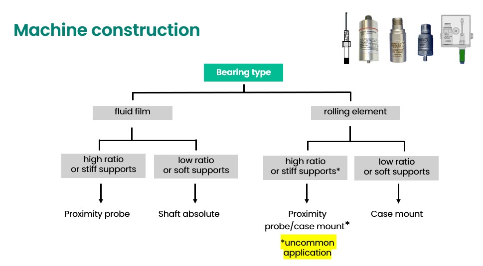
This flow chart below summaries the selection criteria forMachine Construction:
Fluid film bearings are to be equipped with either proximity probes only or shaft absolute based on the casing-to-rotor ratio and support stiffness; whereas rolling element bearings are to be equipped with case-mounted sensors.
* There is a condition for rolling element bearing installations which is not very common when there is a high ratio or stiff support. However,in this very special and rare condition, a proximity probe needs to be mounted on the casing slightly away from the bearing as the bearing vibration will not show any significant vibration amplitudes.
Transducer Selection
Before selecting the transducer, we also need to know which malfunctions are we trying to detect. There are two categories:
- Rotor related malfunctions: The source of the vibration is the rotor itself, or some action or motion that primarily involves the rotor. For example, misalignment, imbalance, fluid-induced instabilities, rub, cracked rotors, and rotor bow are common examples of rotor malfunctions.
- Housing or support related malfunctions: Vibration caused by housing- or support-related malfunctions can often be observed directly on the machine casing. These vibrations can be caused by sources that are external or internal to the machine case like: rolling element bearings, piping forces, structure resonances, support or foundation deterioration, rotor/bearing conditions (loose or tight), rub, and thermal warping
To ensure quality information from the vibration measurements,one important factor is using a transducer system that is capable of covering the expected vibration frequencies that can be generated by the machine/malfunction. To do this we need to examine the following aspects:
- Expected fault frequencies based on machine design
- Frequency response of the vibration transducer
- Effect of the transducer mounting on its linear range
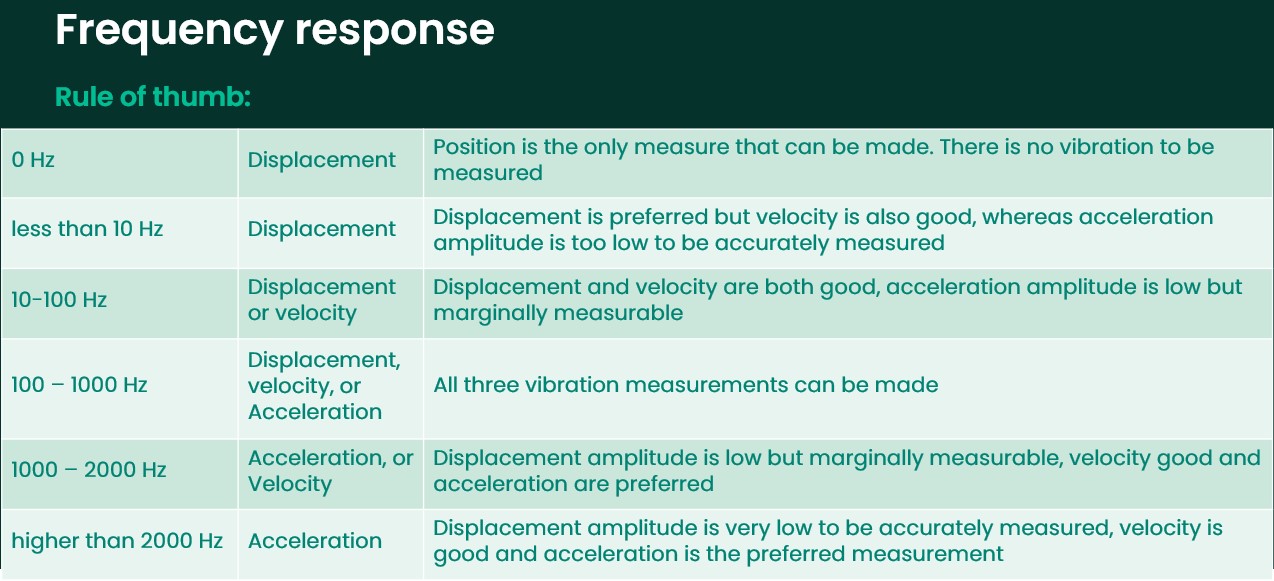
Mathematically, the relationship between Displacement, Velocity and Acceleration is defined via integration and differentiation. However, from a practical point of view, the important parts of the relationship are summarized in the following table:
Finally,the selected transducer must be able to withstand the environment in which it must operates and physical constraints needs to be considered, as there must be enough room to install the transducer at the proper location.
Securing and routing cables, sealing connections, and bracket design must also be considered.
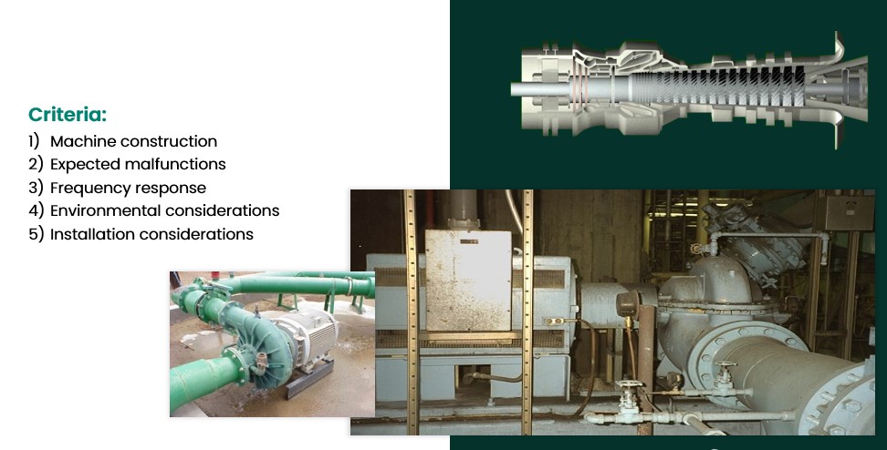
If a machine is designed and built to accept a certain type at certain locations, it is always easiest to use those locations and sensors. However, it may not be the best in terms of accuracy, to use any of those pre-existing mounting points. So, the selection criteria according to machine construction, expected malfunctions, and frequency response should always be considered.Remember, only the right transducer, installed properly at the right locations, will provide good results.
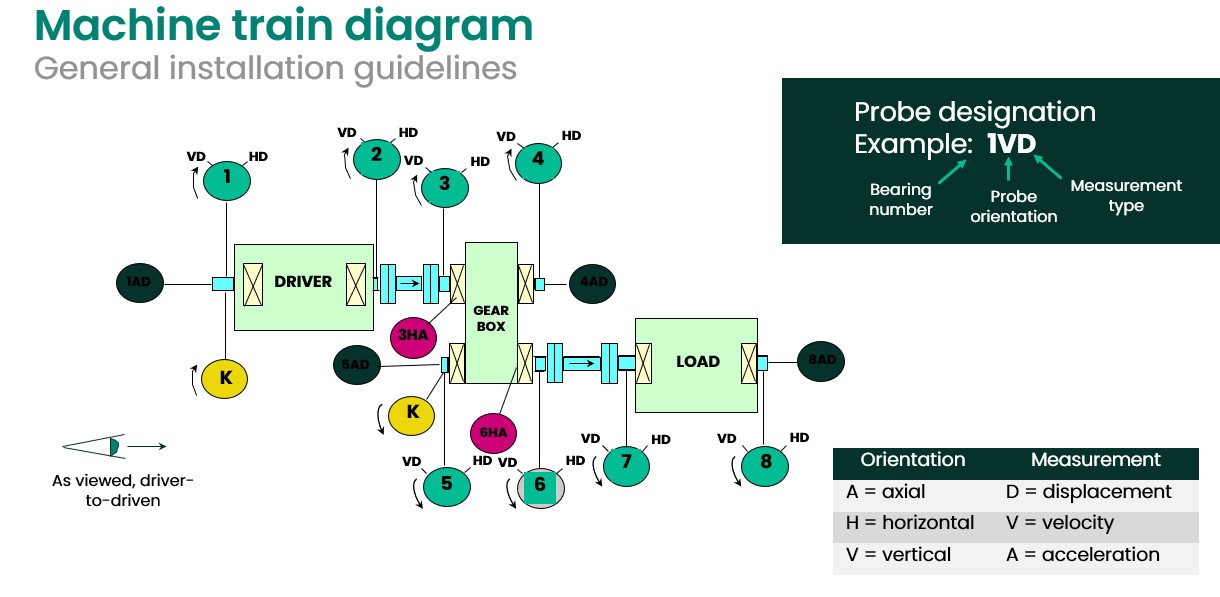
Example:
This is an example of a typical machine train with driver, driven and a gearbox in between, all bearings are of the fluid film variety. In this case, we will typically use the following:
- 2 keyphasors (one for HSS and one for LSS)
- X&Y proximity probes at each bearing
- 2-3 Thrust probes at each thrust bearing
- 2 Accelerometers will be installed at the Gearbox (one at HSS and another at the LSS to detect Gear issues which usually happen at high frequencies)
We hope you found this information useful. As we can see from just this one blog post,the study of vibration and dynamic measurements is a complex one, with multiple factors at play in every machinery installation example. Due to this level of variance, there is rarely a "one size fits all" solution to your enterprise condition monitoring needs. To that end,we at Bently Nevada welcome the chance to talk with you about your vibration measurement concerns and will be happy to help you craft a gameplan to cover your critical assets and improve your overall condition monitoring strategy. Feel free to contact us to start a conversation around your condition monitoring needs.
This training blog was developed in conjunction with the video training series of the Bently Nevada Machinery Diagnostics team. This information is also available with our webinar-on-demand platform, which can be found here.
Source: https://www.bakerhughes.com/bently-nevada/blog/vibration-and-dynamic-measurements

